Understanding Weld Symbol Chart Meanings: A Step-by-Step Guide
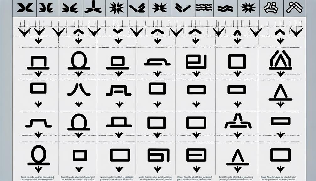
A weld symbol chart is an essential tool for interpreting weld specifications in engineering drawings. These charts include basic symbols such as fillet, groove, plug, and slot welds, each with specific indications for weld size and type.
Fillet welds, depicted as triangles, connect surfaces at right angles. Groove weld symbols specify edge preparation for full penetration.
Plug and slot welds join overlapping pieces through pre-drilled features. Spot and seam weld symbols are pivotal in automotive and sheet metal applications.
Supplementary symbols provide additional details like weld contour and finish, ensuring compliance with engineering standards. Explore further to enhance your understanding.
Key Takeaways
- Basic weld symbols include the reference line, arrow, and tail to convey welding information.
- Fillet weld symbols are a right-angled triangle on the reference line, indicating a triangular cross-section.
- Groove weld symbols specify preparation details for edge-to-edge joints to ensure full penetration.
- Plug and slot weld symbols detail hole diameter, spacing, and number for joining overlapping pieces.
- Supplementary symbols provide additional weld information, including contour, finish, and special instructions.
Basic Weld Symbols
Understanding basic weld symbols is essential for accurately interpreting engineering drawings and ensuring the integrity of welded joints. These symbols serve as a universal language, conveying critical information about the type, size, and location of welds.
Key components include the reference line, arrow, and tail, each providing specific instructions. The reference line is the foundation, indicating the weld type and specifications. Symbols placed above or below this line denote different welding positions. Supplementary symbols may describe additional requirements such as weld contour or finishing methods.
Clarity in these symbols prevents miscommunication, ensuring that all parties involved in fabrication and inspection understand the precise welding requirements. Mastery of basic weld symbols is a fundamental skill for any welding professional.
Fillet Welds
Fillet welds, one of the most common types of welds, are used to join two surfaces at a right angle to each other, forming a triangular cross-section. These welds are prevalent in structural applications due to their simplicity and effectiveness.
The weld symbol for a fillet weld is a right-angled triangle, placed on the reference line of a welding blueprint. The size of the fillet weld is specified by the leg length, which is the distance from the root to the toe of the weld.
Fillet welds can be applied to both lap and T-joints and are known for their ability to withstand high levels of stress. Properly executed, they guarantee structural integrity and longevity.
Groove Welds
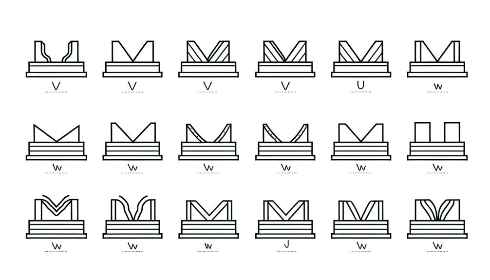
Groove welds, necessary for fusing two workpieces edge-to-edge, are characterized by the type of groove that is prepared on the surfaces to be joined.
Each groove type, including square, V, bevel, U, and J, requires specific preparation and welding techniques to guarantee a strong joint. The choice of groove type is determined by the material thickness, joint configuration, and required weld strength.
Proper groove preparation is vital to achieve full penetration and avoid defects such as lack of fusion or incomplete joint penetration. Welding symbols for groove welds provide detailed instructions on groove shape, dimensions, and welding process, enabling consistent and high-quality welds.
Mastery of these symbols is essential for welders and engineers alike.
Plug and Slot Welds
Plug and slot welds are specialized techniques used to join overlapping metal pieces by filling pre-drilled holes or elongated slots with weld metal. These welds are typically employed when the joined surfaces cannot be accessed from both sides, providing a robust connection without mandating a full penetration weld.
The plug weld is circular and fills a round hole, while the slot weld is elongated, filling a slot. Each type of weld guarantees a firm bond, redistributing stress across the joint. The appropriate weld symbol on engineering drawings includes details such as the diameter or length of the weld, spacing, and number of welds required, ensuring precise execution and achieving the desired structural integrity.
Spot and Seam Welds
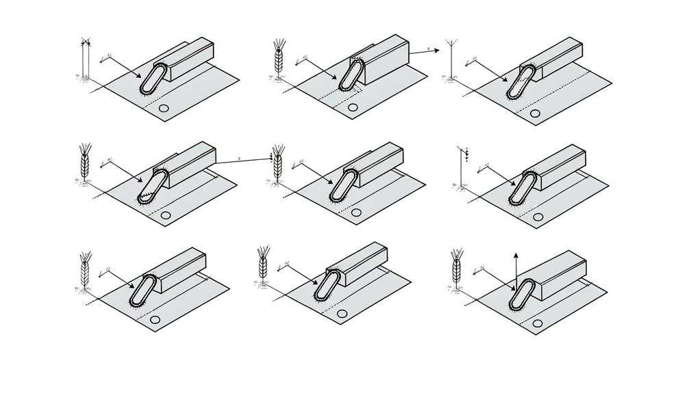
Spot and seam welds are critical in various manufacturing processes, each offering unique strengths and applications.
Understanding the types of spot welds and their corresponding symbols is essential for accurate interpretation and execution.
Additionally, seam weld applications and their notation provide clarity for continuous welds, ensuring structural integrity and adherence to specifications.
Types of Spot Welds
In the field of welding, understanding the distinctions between spot welds and seam welds is important for guaranteeing the integrity and strength of fabricated structures. Spot welds are localized welds typically used where two metal surfaces are pressed together, while seam welds are continuous welds formed along a joint. These welding techniques are vital in various manufacturing processes, from automotive to aerospace industries.
| Type | Description |
|---|---|
| Spot Weld | Localized weld joining two surfaces at discrete points. |
| Seam Weld | Continuous weld formed along the length of a joint. |
| Applications | Used in automotive, electronics, and sheet metal fabrication. |
Understanding these types assures appropriate application, enhancing the durability and reliability of the final product.
Seam Weld Applications
Seam welds find extensive applications across various industries, including automotive, aerospace, and electronics, where continuous joint strength and durability are paramount.
These welds are ideal for creating airtight or watertight seals, making them essential in manufacturing fuel tanks, heat exchangers, and electronic enclosures.
In the automotive industry, seam welds are used for producing car bodies and exhaust systems, ensuring structural integrity and longevity.
Aerospace applications leverage seam welding for critical components that require high precision and reliability.
The electronics industry benefits from seam welds in the assembly of hermetically sealed components, which protect sensitive electronics from environmental exposure.
This welding technique's ability to provide a consistent and robust seam makes it indispensable in high-performance and safety-critical applications.
Symbol Interpretation Basics
Understanding the fundamental principles of weld symbol interpretation is crucial for guaranteeing the accuracy and quality of spot and seam welds in various engineering and manufacturing applications.
Spot weld symbols are depicted as circles, indicating localized fusion points, often used in sheet metal fabrication where high strength is needed.
Seam weld symbols, represented by a continuous line, denote a continuous weld along a joint, suitable for applications requiring airtight or watertight seals.
Precise interpretation of these symbols, including their orientation and supplementary details, is vital in translating design specifications into high-quality welds.
Mastery of these basics guarantees that welders and engineers can collaborate effectively, optimizing both structural integrity and production efficiency.
Surfacing Welds
Surfacing welds serve a critical role in enhancing the surface properties of a workpiece, such as resistance to wear or corrosion. Understanding the purpose and application of surfacing welds is essential for selecting the appropriate weld type for specific requirements.
This section will elucidate the common symbols associated with surfacing welds and their interpretations.
Purpose and Application
Surfacing welds play a crucial role in enhancing the wear resistance, corrosion resistance, and overall lifespan of metal components in various industrial applications. These welds involve the addition of a layer of material onto the surface of a workpiece to improve its properties without altering the core structure.
Commonly used in industries such as mining, construction, and manufacturing, surfacing welds are essential for refurbishing worn-out parts and extending their service life. By applying a specialized alloy or hard-facing material, surfacing welds provide a cost-effective solution for maintaining critical machinery and equipment.
Understanding their purpose and application ensures top-notch performance and durability in demanding environments, thereby reducing downtime and maintenance costs.
Common Symbols Explained
To effectively leverage the benefits of surfacing welds, it is essential to grasp the common symbols used to denote these welds in technical drawings and welding blueprints.
Surfacing welds are represented by a simple rectangular symbol placed on the reference line. This symbol indicates the addition of material to a surface to enhance its wear resistance or to restore dimensions. The symbol's dimensions, such as width and thickness, are vital for conveying the required specifications.
Additionally, surfacing weld symbols may include notations for multiple layers or specific surface finishes. A thorough understanding of these symbols is necessary for ensuring precise communication and execution in welding projects, thereby enhancing the quality and durability of the weldments.
Back and Backing Welds
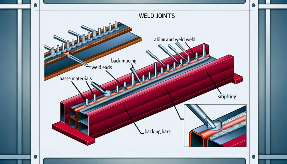
Back and backing welds are essential techniques used in welding to guarantee the integrity and strength of the root of the weld joint. These methods ensure a sound foundation for subsequent weld passes and are critical in preventing defects such as lack of fusion or penetration. Back welds are applied to the reverse side of the initial weld, whereas backing welds involve the use of a material placed at the root to support the primary weld.
| Technique | Purpose |
|---|---|
| Back Weld | Reinforces the root from the opposite side |
| Backing Weld | Provides support during the primary weld |
| Materials | Various metals or consumables |
| Applications | Structural components, piping, vessels |
| Benefits | Enhanced strength, reduced defects |
These practices are foundational in achieving reliable and durable weld joints across various applications.
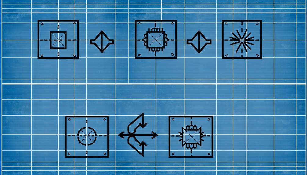
Supplementary Symbols
Supplementary symbols in welding provide additional information about the weld, specifying details such as contour, finish, and other special instructions that enhance the clarity and precision of the welding process. These symbols often include indicators for weld contour (e.g., flat, convex, or concave) and surface finish (e.g., grinding, machining).
For instance, a contour symbol could be a straight line indicating a flat surface, while a finish symbol might denote that the weld needs to be smoothed by grinding. Additional instructions, such as weld-all-around or field weld symbols, further specify the location and conditions under which the weld should be performed.
Understanding these supplementary symbols is essential for ensuring that the welding meets precise engineering and quality standards.
Conclusion
To sum up, understanding the various weld symbols and their meanings is essential for ensuring the integrity and quality of welded structures. Mastery of basic weld symbols, including fillet, groove, plug, slot, spot, seam, surfacing, and back and backing welds, provides a robust foundation for interpreting technical drawings.
Supplementary symbols further enhance this understanding, ensuring precision in communication and execution. As the saying goes, 'A chain is only as strong as its weakest link,' highlighting the critical importance of weld quality in structural integrity.