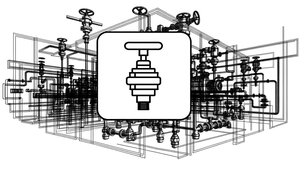
Identifying and Drawing Pressure Switch Symbols in Schematics
The standardized symbol for a pressure switch is integral for consistent representation in engineering diagrams. It promotes clear and accurate communication among multidisciplinary teams, following ISO 1219 and ANSI/ISA-5.1-2009 standards.
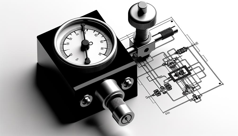
This symbol typically denotes a device that triggers or stops electrical circuits based on particular pressure levels in fluid or gas systems. Components include a pressure sensor, actuator, and electrical contacts.
Standard symbols may vary to illustrate various types of pressure switches, such as differential, vacuum, or hydraulic. Regular usage reduces interpretation errors and improves workflow efficiency.
To grasp specific design intricacies, it is crucial to explore additional resources.
Key Takeaways
- The standard symbol for a pressure switch includes a pressure sensing element and electrical contacts.
- ISO 1219 and ANSI/ISA-5.1-2009 provide standardized symbols for pressure switches.
- Symbols may vary based on pressure switch type, such as differential or vacuum.
- Clear and standardized pressure switch symbols enhance communication and reduce interpretation errors.
- Symbols must be included in engineering diagrams and technical documentation for clarity.
Definition of a Pressure Switch
A pressure switch is a precision device that activates or deactivates an electrical circuit when a specific pressure level is reached. It operates by sensing changes in pressure, typically within a fluid or gas system, and triggering a response based on pre-set thresholds.
Key components include a pressure sensor, actuator, and electrical contacts. Upon reaching the designated pressure, the sensor transmits force to the actuator, causing the contacts to open or close the circuit. This mechanism ensures the controlled operation of various systems, from industrial machinery to HVAC units.
Pressure switches are integral in applications requiring precise pressure monitoring and control, enhancing system reliability and safety. Their design varies to accommodate different pressure ranges and environmental conditions.
Importance in Engineering Diagrams
The inclusion of standardized pressure switch symbols in engineering diagrams is essential for maintaining uniformity across technical documentation.
This standardization enhances communication clarity among multidisciplinary teams, ensuring all stakeholders interpret the diagrams consistently.
Consequently, it reduces interpretation errors, leading to more efficient project execution and system reliability.
Standardization in Engineering Diagrams
In engineering diagrams, standardization promotes uniformity and clarity, facilitating effective communication among engineers and stakeholders. Adhering to established standards, such as ANSI, ISO, and IEC, ensures that symbols and notations are universally understood, reducing the risk of misinterpretation. This practice is crucial in maintaining consistency across various projects and disciplines.
| Standard | Organization | Description |
|---|---|---|
| ANSI | American National Standards Institute | Develops and accredits engineering standards in the U.S. |
| ISO | International Organization for Standardization | Sets international standards across multiple industries. |
| IEC | International Electrotechnical Commission | Standardizes electrical and electronic technologies. |
Enhancing Communication Clarity
Effective communication in engineering diagrams hinges on the clarity of symbols and notations, ensuring all stakeholders can accurately interpret technical information.
Clear representation of a pressure switch symbol is pivotal, as it facilitates precise comprehension among engineers, technicians, and project managers.
Utilizing standardized symbols minimizes ambiguities, fostering a mutual understanding across multidisciplinary teams.
Engineering diagrams with unambiguous symbols enhance workflow efficiency and reduce the likelihood of miscommunication.
Symbols should be universally recognizable and adhere to established industry standards, such as those set by ISO or ANSI.
Consequently, investing effort in clear, standardized diagrammatic representation is essential for maintaining operational integrity and achieving project success in engineering environments.
Reducing Interpretation Errors
Minimizing misinterpretation errors in engineering diagrams is crucial for guaranteeing accurate implementation and operational safety. Clear, standardized symbols, such as those for pressure switches, lessen the risk of miscommunication among multidisciplinary teams.
Consistency in symbol usage enhances the readability and dependability of technical documents, reducing the likelihood of costly mistakes. Employing universally recognized standards, like ISO 1219 for fluid power systems and components, guarantees uniformity across design schematics.
Additionally, proper documentation and legend inclusion are indispensable for elucidating specific symbol meanings. Adhering to these practices not only simplifies maintenance and troubleshooting but also facilitates compliance with industry regulations.
Ultimately, minimizing misinterpretation errors fosters a safer and more efficient engineering environment.
Basic Components
A pressure switch primarily consists of a sensing element, a setpoint adjuster, and electrical contacts that respond to pressure changes.
The sensing element detects variations in pressure within the system, typically through a diaphragm, piston, or bourdon tube.
The setpoint adjuster allows users to calibrate the switch to activate or deactivate at a specific pressure threshold.
Electrical contacts, integral to the switch, open or close circuits in response to the sensed pressure, thereby controlling external devices or systems.
These components collectively guarantee the pressure switch functions reliably, maintaining system integrity and safety.
Understanding these fundamental elements is pivotal for accurate interpretation and application in various industrial settings.
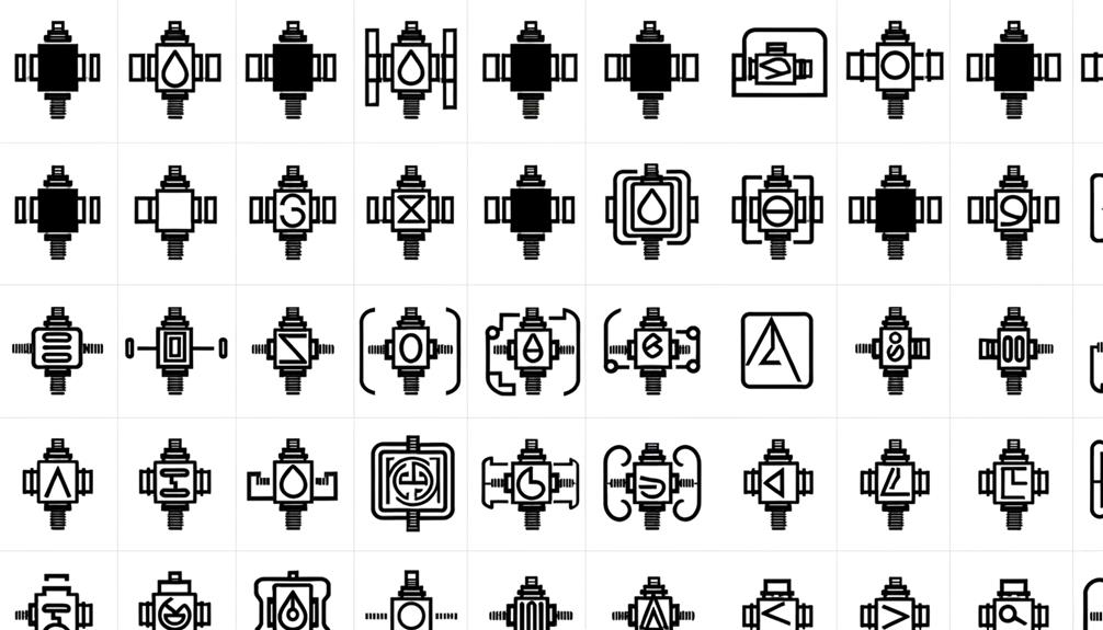
Standard Symbols
Standard symbols for pressure switches adhere to common industry standards such as ISO and ANSI, ensuring uniformity across technical diagrams.
Effective diagrammatic representation techniques are essential for accurate communication of system design and functionality.
Variations in symbols are explained to accommodate different types of pressure switches and specific application requirements.
Common Industry Standards
Frequently, the representation of pressure switches follows standardized symbols outlined by industry guidelines such as ISO 1219 and ANSI/ISA-5.1-2009. These standards guarantee uniformity and clarity in technical drawings, promoting effective communication across engineering and maintenance teams.
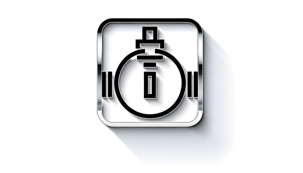
ISO 1219 specifies graphical symbols for fluid power systems and their components, while ANSI/ISA-5.1-2009 provides standardized symbols for instrumentation and process diagrams. The pressure switch symbol typically includes a diamond shape intersected by a diagonal line, often accompanied by a pressure reference designation.
Adherence to these standards reduces potential misinterpretations, ensuring that all stakeholders have a precise understanding of the system's components and their functions. This standardization is vital for maintaining operational efficiency and safety in industrial environments.
Diagrammatic Representation Techniques
Diagrammatic representation techniques employ standardized symbols to convey complex information efficiently and accurately within technical diagrams. These symbols are integral to engineering, electrical, and mechanical fields, ensuring unambiguous communication among professionals.
Standard symbols, such as those outlined by the International Electrotechnical Commission (IEC) or the American National Standards Institute (ANSI), are universally recognized and eliminate potential misinterpretations. For instance, a pressure switch symbol typically consists of a combination of a pressure gauge and a switch, encapsulating both its function and operational context.
Utilizing standardized symbols streamlines the design, troubleshooting, and maintenance processes, ultimately enhancing system reliability and safety. Mastery of these symbols is essential for professionals to interpret and create technical diagrams effectively.
Symbol Variations Explained
Understanding the variations of standard symbols is vital for accurately interpreting technical diagrams across different engineering disciplines.
Pressure switch symbols can vary based on the specific standards adopted by industries such as ISO, ANSI, or IEC. For instance, the ISO symbol typically includes a triangle touching a line, denoting the actuation point, whereas the ANSI symbol might use a different geometric configuration, such as a square or circle.
These subtle differences can impact the interpretation of diagrams, affecting the design, troubleshooting, and maintenance processes.
Familiarity with these symbol variations guarantees that professionals can seamlessly navigate across diverse documentation, enhancing accuracy and efficiency in their technical work.
As a result, mastering these variations is vital for effective communication and operational consistency.
Variations and Types
Pressure switch symbols can differ greatly based on the specific type and application of the pressure switch utilized. Common types include differential, vacuum, and hydraulic pressure switches, each represented by distinct symbols.
Differential pressure switches, which monitor the difference between two pressure points, often use a symbol featuring two pressure inputs.
Vacuum pressure switches, designed for low-pressure applications, typically have a distinct symbol indicating negative pressure.
Hydraulic pressure switches, used in fluid power systems, often incorporate symbols indicative of fluid flow and pressure thresholds.
Additionally, variations may arise from the switch's electrical characteristics, such as normally open (NO) or normally closed (NC) configurations. Understanding these variations is essential for accurate schematic interpretation and system integration.
How to Read the Symbol
Interpreting a pressure switch symbol requires familiarity with the standard graphical representations and notations used in technical schematics. Typically, a pressure switch symbol combines elements that denote its function and operational state.
The primary symbol often includes a rectangle representing the switch body, with an arrow or line indicating the actuation mechanism based on pressure changes. Contacts within the symbol, either normally open (NO) or normally closed (NC), are depicted using standard electrical symbols.
Key details, such as setpoint pressures and switching thresholds, are sometimes annotated near the symbol. Understanding these components and their interrelations is essential for accurate interpretation and application within system diagrams, ensuring proper integration and functionality of the pressure switch in various control systems.
Common Applications
In various industrial and commercial settings, pressure switches are employed extensively to monitor and control fluid systems by responding to changes in pressure levels.
Common applications include hydraulic and pneumatic systems, where maintaining ideal pressure is essential for operational efficiency and safety.
HVAC systems utilize pressure switches to regulate air flow and refrigerant cycles.
In water treatment facilities, these devices guarantee proper pressure within filtration and distribution systems.
Additionally, pressure switches are crucial in automotive applications for monitoring oil and fuel systems.
In process industries, they safeguard equipment by triggering alarms or shutting down machinery when pressure thresholds are breached.
Their versatility and reliability make pressure switches indispensable in maintaining system integrity and operational continuity across diverse sectors.
Troubleshooting Tips
Effective troubleshooting of pressure switches involves systematically checking electrical connections, pressure settings, and mechanical components to identify and resolve issues. An organized approach guarantees that potential problems are efficiently diagnosed and rectified.
Key steps include:
- Inspect Electrical Connections: Verify that all wiring is intact and connected properly to avoid intermittent faults.
- Check Pressure Settings: Guarantee the switch is set to the correct pressure range for the application.
- Test Mechanical Components: Examine diaphragms, springs, and other parts for wear or damage.
- Evaluate Sensor Accuracy: Use calibrated equipment to confirm the pressure sensor's accuracy.
- Review Manufacturer Specifications: Cross-check the switch's configuration against the manufacturer's guidelines to secure proper setup.
Best Practices
Adopting best practices for pressure switch maintenance and operation promotes longevity, reliability, and peak performance in industrial applications. Regular calibration maintains accuracy, while periodic inspections can identify wear or damage early.
Utilize manufacturer guidelines for setting pressure ranges to avoid overloading. Employing proper sealing techniques prevents leaks and contamination, protecting switch integrity. Electrical connections should be routinely checked for corrosion and secure attachment.
Implementing a maintenance log aids in tracking service intervals and component replacements. Additionally, training personnel on correct handling and operational procedures minimizes human error.
Additional Resources
To further enhance comprehension of pressure switch symbols, consider consulting specialized blog posts and industry standards. These resources provide detailed explanations and visual representations, aiding in the accurate interpretation and application of these symbols.
For more targeted information, refer to subtopics focusing on specific use cases and symbol variations.
[BLOG POST TITLE
For those seeking further knowledge on pressure switch symbols, the following resources provide in-depth analysis and technical guides. These materials are invaluable for professionals aiming to deepen their understanding of schematic representations and operational principles.
- International Electrotechnical Commission (IEC) Standards: Detailed guidelines and standards for pressure switch symbols.
- National Fluid Power Association (NFPA Guides: Thorough manuals on fluid power system symbols, including pressure switches.
- Instrumentation and Control Engineering Textbooks: Academic resources offering detailed explanations and examples.
- Online Technical Forums: Platforms like Control.com where industry experts discuss and troubleshoot pressure switch symbol interpretations.
- Manufacturer Datasheets: Detailed specifications and symbol explanations directly from pressure switch manufacturers.
These resources guarantee a solid grasp of pressure switch symbols, essential for accurate system design and troubleshooting.
Symbol for a Pressure Switch
Accessing additional resources on the symbol for a pressure switch can greatly enhance one's comprehension of its integration within complex systems. Industry-standard references such as ISO 1219 and IEC 60617 provide detailed guidelines and schematic representations essential for accurate documentation and interpretation.
These resources elucidate the graphical depiction of pressure switches, often involving a combination of geometric shapes and annotations to denote operational characteristics. Technical manuals, engineering textbooks, and specialized online databases also offer valuable insights into symbol standardization and application.
SUBTOPIC
Industry professionals can enhance their technical proficiency through extensive resources such as standards manuals, technical databases, and specialized engineering literature. These resources provide precise guidelines and detailed information essential for correctly interpreting and implementing pressure switch symbols in technical drawings and schematics.
Notable resources include:
- ISO Standard 1219-1: Fluid power systems and components – Graphic symbols and circuit diagrams.
- IEEE Standards: Specifically, the IEEE 315-1975 (Reaffirmed 1993) for graphical symbols.
- NFPA 79: Electrical Standard for Industrial Machinery, which includes symbols for control circuit devices.
- ASHRAE Handbook: A detailed guide for HVAC systems, including pressure switch applications.
- Technical Databases: Platforms like Engineering Village and IEEE Xplore provide access to peer-reviewed papers and industry standards.
These tools ensure precise and thorough communication in engineering documentation.
Conclusion
The symbol for a pressure switch, a vital element in engineering diagrams, encapsulates a world of intricate functionality. Its representation, standardized yet varied, conceals the complexities of mechanical and electrical integration.
Applications span across industries, ensuring operational safety and efficiency. Mastery of its troubleshooting and best practices is essential.
What secrets lie within these diagrams? What unseen forces do they control? The symbol of a pressure switch is more than a mere icon; it is a gateway to understanding advanced engineering systems.


밤알바를 하다보면 어떤 가게에서 일을 해야하는지 고민하는 경우가
많습니다.
Have a look at my weeb page … 퀸알바
Your point of view caught my eye and was very interesting. Thanks. I have a question for you. https://www.binance.com/register?ref=IHJUI7TF
만약, 지금 일하고 있는 가게를 옮기고 싶거나, 처음
일하는 언니들을 위해, 다음과 같은 선별 기준으로 밤알바 업소를 추천하고 있습니다.
Heere is my webpage 룸알바 고소득 일자리 정보
검토했어요 배구 경기 보기 어쨌든 영어 해설도 있나요 최고예요
스포츠플랫폼|스포츠중계|스포츠무료중계|해외스포츠중계|해외축구중계|축구중계|해외축구무료중계|무료스포츠중계|무료중계|축구무료중계|실시간스포츠|해외축구|epl중계|축구생중계|스포츠중계무료|nba중계|mlb중계|스포츠무료보기|스포츠실시간|무료스포츠|해축중계|무료야구중계|야구중계|야구무료중계|해외중계|실시간중계|경기방송|생중계방송|실황중계|스포츠방송|경기실황|중계방송|라이브방송|스트리밍중계|경기영상|방송영상|스포츠채널|중계채널|방송링크|시청링크|경기시청|온라인스포츠|인터넷중계|웹중계|모바일중계|스포츠TV|경기보기|중계보기|방송보기|스포츠시청|라이브스포츠|실시간방송|생방송|경기스트리밍|스포츠스트리밍|중계사이트|방송사이트|스포츠플랫폼|중계플랫폼|온라인방송|인터넷방송|스포츠라이브|경기라이브|중계서비스|방송서비스|스포츠영상|경기중계방송|실황방송|라이브중계|온라인경기|인터넷경기|공짜중계|무과금중계|프리중계|무료시청|공짜시청|무료방송|무료링크|공짜방송|무료스트리밍|프리스트리밍|고화질중계|HD중계|4K중계|초고화질|풀HD중계|버퍼링없는중계|끊김없는중계|안정적중계|고속중계|빠른중계|해외경기|해외리그|국제경기|글로벌스포츠|월드스포츠|축구생방송|야구생방송|농구생방송|배구생방송|골프생방송|스포츠다시보기|경기다시보기|재방송|하이라이트|경기요약|모바일스포츠|PC중계|태블릿중계|스마트폰중계|모바일시청|프리미어리그무료중계|라리가무료중계|분데스리가중계|세리에A중계|챔피언스리그중계|유로파리그중계|K리그중계|아시안컵중계|KBO무료중계|일본야구중계|대만야구중계|메이저리그무료|NBA무료중계|미국농구중계|KBL중계|한국농구중계|V리그중계|여자배구중계|남자배구중계|배구무료보기|PGA중계|LPGA중계|골프무료중계|테니스중계|UFC중계|복싱중계|격투기중계|e스포츠중계|올림픽중계|월드컵중계|아시안게임중계|국제대회중계|해외축구실시간|해외야구실시간|해외농구실시간|프리미어리그생중계|라리가생중계|챔스무료중계|EPL중계|리그앙중계|네이션스리그중계|국가대표축구중계|코파아메리카중계|클럽월드컵중계|AFC챔피언스리그중계|J리그중계|MLS중계|NBA플레이오프중계|MLB포스트시즌중계|프로야구중계|스포츠중계사이트추천|무료중계링크모음|스포츠방송링크|해외스포츠무료시청방법|스포츠중계어플추천|중계사이트순위|고화질스포츠중계사이트|버퍼링없는중계사이트|안정적인중계|스포츠생중계무료보기|해외축구무료시청|실시간축구중계무료|무료스포츠스트리밍사이트|스포츠라이브방송|경기실시간보기|해외스포츠방송링크|스포츠중계링크공유|중계사이트모음|스포츠무료보기사이트|해외경기무료시청|라이브스포츠무료|스포츠중계베스트|중계사이트TOP|추천중계사이트|농구중계|배구중계|골프중계|F1중계|모터스포츠중계|복싱중계|롤중계|발로란트중계|오버워치중계|배틀그라운드중계|국제대회중계|오늘스포츠중계|지금중계|실시간중계방송|라이브중계방송|새벽스포츠중계|심야중계|밤경기중계|새벽경기|24시간스포츠중계|365일중계|연중무휴중계|주말경기중계|평일중계|토요일중계|일요일중계|오늘경기일정|실시간경기|지금하는경기|라이브경기|새벽축구|심야야구|밤농구|새벽해축|국내리그중계|해외리그중계|고화질무료중계|HD스포츠중계|4K중계방송|초고화질방송|풀HD중계|UHD중계|고품질중계|화질좋은중계|끊김없는스포츠중계|안정적인방송|버퍼링제로|고속스트리밍|멀티앵글중계|다채널중계|동시중계|복수화면중계|1080p중계|무광고중계|광고적은중계|초고화질중계|스포츠중계사이트|중계링크|방송링크|시청링크|스포츠중계어플|중계앱|방송앱|모바일중계앱|PC중계사이트|웹중계|브라우저중계|온라인중계사이트|스포츠중계채널|TV중계|케이블중계|인터넷TV|스포츠OTT|중계플랫폼|스트리밍플랫폼|실시간축구중계|해외축구무료중계|프리미어리그중계|스포츠중계베스트10|TOP5중계사이트|추천순위|인기중계사이트|최고의중계|베스트중계|2026년최신중계|신규중계사이트|최신중계링크|검증된중계사이트|안전한중계|믿을수있는중계|라리가중계|챔피언스리그무료중계|유로파리그무료중계|한국스포츠중계|국내중계|해외스포츠중계무료|글로벌스포츠방송|월드스포츠중계|국제경기중계|영어중계|한국어중계|해설중계|무해설중계|미국스포츠중계|유럽스포츠중계|아시아스포츠중계|세리에mazgtv
진짜 공감해요, 증거가 없으면 소송도 어렵다고
해서 흥신소 찾았어요— 비용도 사전에 명확하게 알려주더라고요 다만 합법 범위
안에서 깔끔하게 진행됐어요 도움 되시길 바라요
Christina
체크했어요 스포츠중계 관련해서 궁금했는데 개인적으로 무료로
가능한가요 최고예요
경기분석|스포츠중계|스포츠무료중계|해외스포츠중계|해외축구중계|축구중계|해외축구무료중계|무료스포츠중계|무료중계|축구무료중계|실시간스포츠|해외축구|epl중계|축구생중계|스포츠중계무료|nba중계|mlb중계|스포츠무료보기|스포츠실시간|무료스포츠|해축중계|무료야구중계|야구중계|야구무료중계|해외중계|실시간중계|경기방송|생중계방송|실황중계|스포츠방송|경기실황|중계방송|라이브방송|스트리밍중계|경기영상|방송영상|스포츠채널|중계채널|방송링크|시청링크|경기시청|온라인스포츠|인터넷중계|웹중계|모바일중계|스포츠TV|경기보기|중계보기|방송보기|스포츠시청|라이브스포츠|실시간방송|생방송|경기스트리밍|스포츠스트리밍|중계사이트|방송사이트|스포츠플랫폼|중계플랫폼|온라인방송|인터넷방송|스포츠라이브|경기라이브|중계서비스|방송서비스|스포츠영상|경기중계방송|실황방송|라이브중계|온라인경기|인터넷경기|공짜중계|무과금중계|프리중계|무료시청|공짜시청|무료방송|무료링크|공짜방송|무료스트리밍|프리스트리밍|고화질중계|HD중계|4K중계|초고화질|풀HD중계|버퍼링없는중계|끊김없는중계|안정적중계|고속중계|빠른중계|해외경기|해외리그|국제경기|글로벌스포츠|월드스포츠|축구생방송|야구생방송|농구생방송|배구생방송|골프생방송|스포츠다시보기|경기다시보기|재방송|하이라이트|경기요약|모바일스포츠|PC중계|태블릿중계|스마트폰중계|모바일시청|프리미어리그무료중계|라리가무료중계|분데스리가중계|세리에A중계|챔피언스리그중계|유로파리그중계|K리그중계|아시안컵중계|KBO무료중계|일본야구중계|대만야구중계|메이저리그무료|NBA무료중계|미국농구중계|KBL중계|한국농구중계|V리그중계|여자배구중계|남자배구중계|배구무료보기|PGA중계|LPGA중계|골프무료중계|테니스중계|UFC중계|복싱중계|격투기중계|e스포츠중계|올림픽중계|월드컵중계|아시안게임중계|국제대회중계|해외축구실시간|해외야구실시간|해외농구실시간|프리미어리그생중계|라리가생중계|챔스무료중계|EPL중계|리그앙중계|네이션스리그중계|국가대표축구중계|코파아메리카중계|클럽월드컵중계|AFC챔피언스리그중계|J리그중계|MLS중계|NBA플레이오프중계|MLB포스트시즌중계|프로야구중계|스포츠중계사이트추천|무료중계링크모음|스포츠방송링크|해외스포츠무료시청방법|스포츠중계어플추천|중계사이트순위|고화질스포츠중계사이트|버퍼링없는중계사이트|안정적인중계|스포츠생중계무료보기|해외축구무료시청|실시간축구중계무료|무료스포츠스트리밍사이트|스포츠라이브방송|경기실시간보기|해외스포츠방송링크|스포츠중계링크공유|중계사이트모음|스포츠무료보기사이트|해외경기무료시청|라이브스포츠무료|스포츠중계베스트|중계사이트TOP|추천중계사이트|농구중계|배구중계|골프중계|F1중계|모터스포츠중계|복싱중계|롤중계|발로란트중계|오버워치중계|배틀그라운드중계|국제대회중계|오늘스포츠중계|지금중계|실시간중계방송|라이브중계방송|새벽스포츠중계|심야중계|밤경기중계|새벽경기|24시간스포츠중계|365일중계|연중무휴중계|주말경기중계|평일중계|토요일중계|일요일중계|오늘경기일정|실시간경기|지금하는경기|라이브경기|새벽축구|심야야구|밤농구|새벽해축|국내리그중계|해외리그중계|고화질무료중계|HD스포츠중계|4K중계방송|초고화질방송|풀HD중계|UHD중계|고품질중계|화질좋은중계|끊김없는스포츠중계|안정적인방송|버퍼링제로|고속스트리밍|멀티앵글중계|다채널중계|동시중계|복수화면중계|1080p중계|무광고중계|광고적은중계|초고화질중계|스포츠중계사이트|중계링크|방송링크|시청링크|스포츠중계어플|중계앱|방송앱|모바일중계앱|PC중계사이트|웹중계|브라우저중계|온라인중계사이트|스포츠중계채널|TV중계|케이블중계|인터넷TV|스포츠OTT|중계플랫폼|스트리밍플랫폼|실시간축구중계|해외축구무료중계|프리미어리그중계|스포츠중계베스트10|TOP5중계사이트|추천순위|인기중계사이트|최고의중계|베스트중계|2026년최신중계|신규중계사이트|최신중계링크|검증된중계사이트|안전한중계|믿을수있는중계|라리가중계|챔피언스리그무료중계|유로파리그무료중계|한국스포츠중계|국내중계|해외스포츠중계무료|글로벌스포츠방송|월드스포츠중계|국제경기중계|영어중계|한국어중계|해설중계|무해설중계|미국스포츠중계|유럽스포츠중계|아시아스포츠중계|세리에경기분석